Natural and Intuitive

In mid-2008, I spent a stimulated series of days working with the founder and chairman of our firm, Sir Nicholas Grimshaw, developing a mixed-use tower in a prominent Manhattan location.
During the previous weekend, I had made the decision to transfer a number of our design decisions for the tower into a computational model in GenerativeComponents. The reasons ranged from the methodological to the practical: by working with the model dynamically within an associative geometry environment we could embed a range of site requirements and design decisions into a well-defined design-space for creative exploration. Significantly decreasing the feedback loop resulted in increasing design iterations for the team. This well-defined design space afforded us the confidence that all iterations would satisfy the requirements posed by the site and program challenges, and we could turn our attention to the possible geometric variations that best exemplified the building’s intended character. The design geometry was rigorous; from years of working on projects with complex geometries, any reduction to the manual re-modeling of rigorous geometric systems simply due to a parameter change was an immediate time-saver.
When Nick sat down at my desk to review the design, I spent a minute explaining what he was seeing on my screen. On the left monitor was a basic geometric model showing the visual results of each parameter and how it affected the building’s geometric profile. On the right monitor was a collection of control sliders (geometric control & program distributions), input parameters (zoning requirement, right-to-light rules), and a dynamically updated spreadsheet estimating per-floor and per-program square footages and potential building costs. Having spent 14 years honing my digital design skills, with the previous 5 focused on advancing algorithmic techniques, it was a welcome surprise to experience an entirely unimpressed Nick while I manipulated this range of parameters in a geometric control jig. With symbolic diagrams, data, and shaded viewports spread across two large screens, the discussion centered entirely on design explorations, not on the technology on the screen. For Nick, this usage of associative geometry was a direct manifestation of the design methodology Grimshaw Architects was founded upon, simply in digital form. It was natural and intuitive. All I had done was embed our design process, through diagrams and formal relationships, into a digital model available to us for iterative design.
This story exemplifies the concept behind how our firm, and specifically those who are part of our Computational Design Unit (CDU), work as digital tool builders and developers of design-spaces in the pursuit of architecture. The creation of rule systems through algorithms grounded in the realities of site, program, material, and construction is rooted in our past history of formal geometric systems as influenced by industrial design fabrication. Manifesting these rule systems through three-dimensional associative modeling, where digital objects in the scene are embedded with properties and rules through complex relationships to other objects, is a natural fit for our design methodology. At Grimshaw, the advent of this entire technique, often called computational design, was not a paradigm shift in architectural expression; it developed as a tool that allows us to embed design intelligence rooted in the office’s design methodology as it has existed for almost 30 years.
Laying the groundwork
The International Terminal at Waterloo laid the groundwork for Grimshaw’s use of associative geometric systems. Sir Nicholas’ earliest work demonstrated the tenants of First Principals design methods as expressed within the British High-Tech architectural movement: expression of material properties and structural forces, and performance-driven design through a pervasive examination of energy and environmental affect. Through a love of the archetypal industrial shed”, numerous early projects were developed as a kit-of-parts: bespoke industrial design objects systematized to create space. The desire at Waterloo was to create a logical system for spanning multiple train tracks in an open-air station within the constraints of an eccentric site. Taking its cues from Brunel’s train sheds yet reflecting the construction methods and materials of the modern day, Waterloo’s kit-of-parts system was not developed based on explicit measurements, but instead on a collection of implicit rules and relationships between parts.
The template was simple: two bowstring trusses spanning over the tracks, following the changing site boundary from one end to the other [FIG 1]. While making the truss arcs tangential for the entire length of the changing site boundaries resulted in unique trusses at each junction, the implicit rule-based system made the instructions for developing each truss clear. This system was further developed using early CAD technology through the assistance of engineer YRM Anthony Hunt Associates. The result is complex without being complicated. The International Terminal at Waterloo is collection of rigorous structural and geometric rules overlapping to create a visually unique structure [FIG 2].

Figure 1 - Waterloo International Terminal - Geometry Diagram

Figure 2 - Waterloo International Terminal - Photo by Jo Reid & John Peck
Waterloo’s influence over the development of design systems went beyond Grimshaw. Years later, the same group of individuals at YRM who developed the structural CAD models resulting in Waterloo’s geometric rules, formed the SmartGeometry Group. The founding directors of the SmartGeometry Group, Hugh Whitehead (Foster + Partners), J Parrish (Arup Sport), Lars Hesselgren (PLP), and Robert Aish (then of Bentley Systems, now Autodesk), sought to re-invigorate the usage of algorithmic design techniques explored at Waterloo within the architectural and engineering professions through the development of CAD associative modeling tools. The SmartGeometry Group, working with Bentley System’s R&D, helped to develop the pioneering computational design software GenerativeComponents, for which Waterloo Station provided an early testing prototype [FIG 3]. Now, through a yearly international workshop and conference, the SmartGeometry Group continues this development with the next generation of computational designers.
Figure 3 - Prototype of Waterloo International Terminal in an early version of GenerativeComponents, by Robert Aish (then at Bentley)
The Development of Design Computation at Grimshaw
Computational tools, including both direct modeling for design exploration and visualization, and algorithmic modeling for complex systems, have become increasingly commonplace at Grimshaw over the past 5 years. Direct modeling, the process of 3D modeling each geometric object based on explicit coordinates, has been the standard design tool in this office for many years. Despite regular use of formal geometric systems to develop building forms following Waterloo, these rule systems were unable to be embedded in the digital model due to software limitations, thus Grimshaw suffered from the typical problems associated with direct 3D modeling. Rules and algorithms, documented external to the 3D model through diagrams in sketchbooks, were implemented at each design iteration, resulting in hours (or sometimes days) of manual remodeling as conditions or design intent changed. Each parameter change essentially required the designer to hit the delete key and start from scratch, following each rule down the line again to completion, only to have more parameters change the next day. With a constant need to visualize the ever-changing design as it progressed, this time-consuming process was a necessary evil.

Figure 4 - Eden's ERC building Phylotaxis Pattern
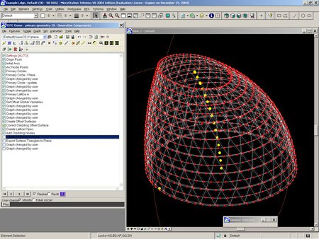
Figure 5 - Fulton Street - Generative Components Model
As opposed to modeling the solution directly, associative modeling enables the designer to set up relationships and restrictions from which the design will result. In essence, you are embedding the designers’ thinking into an active model - the creation of a design-space where every result satisfies the requirements of the design up front, freeing one to explore solutions playfully.
Early testing and development of associative modeling systems occurred between the New York and London offices in 2003 beginning with the roof design of Eden’s Educational Resource Center. Based on the Phylotaxis pattern found in sunflowers, the roof geometry and panelization was developed with an early alpha version of GenerativeComponents as a collaboration between a junior staff member and our structural engineer at the first SmartGeometry Workshop [FIG 4]. In New York, the early development of the dome in the Fulton Street Transit Center added additional layers of control to the computational design process via natural light analysis and fabrication output [FIG 5]. On Fulton Street, seemingly banal elements such as the inclusion of OSHA regulations as an input parameter for a maintenance access ramp demonstrated the power of the system to aide in solving a wide range of design problems.
During subsequent projects, the use of a associative modeling tools began to yield a different model for iterative design both in how teams interacted with our engineers who were focused on analysis, but also within the team structure inside Grimshaw. I was consulted on a regular basis to create a digital tool to be used by the team in developing their design much in the same way a woodworker will develop a control jig to limit aspects of the fabrication process. After the creation of a well-developed jig and clear control system, the team would take complete ownership over further iterations within this design space, confident all iterations would meet the requirements of the design as embedded in the jig.
On the Museo de Acero (Museum of Steel) in Monterrey, Mexico, associative modeling systems were used to develop two elements in the design: a steel folded plate roof structure, and an exterior louver cladding system. For the folded plate roof [FIG 6], a simple set of geometric rules based upon a circular array of points projected on inclined planes set out the initial geometry. From there, flat panels connecting the point arrays were constructed, and a slider and variable-based control panel was created allowing the team a wide range of adjustability within the system. Sliders, akin to volume controls on a recording studio mixing board, are very common amongst associative modeling tools as a way to iterate across a range of input numbers, viewing their impact on the model dynamically. It wasn’t long until the team developed a tight feedback loop with their structural engineers, Werner Sobek. The design team would receive the results from the finite-element analysis suggesting adjustments in plate arrangements and fold depths, changes would be made dynamically in the model, and a new model would be exported for analysis within minutes for another round of analysis. The final design was flattened using simple unfolding algorithms, handed to the contractor for fabrication, and a set of assembly drawings deriving angles and coordinates from the digital model were created.

Figure 6 - Design, analysis, and fabrication process for the Museo del Acero Gallery Roof
The louver system for the exterior of the Museo del Acero [FIG 7] was an opportunity to develop a more sophisticated and expressive control system for geometry. Rather than be limited by the 1-dimensional control provided by sliders, and more tactile system was used to manipulate louver rotation by way of a 3-dimensional control surface. Taking the inherent smoothing properties of a nurbs surface, points on a control surface were mapped directly to the panels. Any change in z-depth for the control surface resulted in a rotated panel within certain constraints. With the project architect in front of the screen, we willfully manipulated the control surface to create a sequence of blended louver openings aligned with windows and view axis. This model was then live-linked with the final construction output, a simple spreadsheet listing each louver’s alpha-numeric code and its corresponding rotation value. Within two days, the sub-contractor was onsite with a printed version of the spreadsheet, rotating the louvers into place.

Figure 7 - Geometric Control System for the Museo del Acero Cast Hall Cladding
The Computational Design Unit

Figure 9 - AMG Stair geometry control

Figure 10 - AMG Stair rendering
For a number of years, computational design tasks were completed by me and eventually a small group of dedicated staff. This resulted in the founding of a more formal group called the Computation Design Unit (CDU). An applied research and development group created to structure work with new digital design tools, the CDU’s scope includes advanced geometric and associative modeling, early environmental analysis, fabrication, and visualization. This arrangement, common in a number of larger architecture and engineering firms, persisted for 2 years. Recognizing the landscape of computational design was changing, a new model for the CDU was necessary.
As algorithmic workflows began to become part of the standard academic curriculum in universities around the world, we began to find junior staff were quicker to engage such processes on a regular basis. In recognition that our teams were requiring more regular and dedicated staff to manage algorithmic workflows as embedded in associative modeling tools, the CDU moved to a distributed model with project-embedded designers. Staff who are members of the CDU play two roles: they act as a computational designer for their projects working directly within the team, and they also engage in general R&D covering the topic of Project Technology. While we have not implemented the Google 10% model for personal projects or R&D, we have engaged in topic-related group development of techniques. Recent general group development has yielded a number of repeat-use systems focused on patterning and panelization. In many cases these systems are developed initially as bespoke tools for a competition or project design study, but are subsequently generalized for reuse through the cleaning up of code and descriptive annotations within the symbolic diagrams. Another team is able to take this new generalized tool and re-use it on their own project to achieve similar effects.
With the addition of a 3D printer and laser cutter as a regular tool in our design arsenal, junior architects experienced with computational design tools encounter fabrication issues early on. Model making has served as an educational tool through direct contact with material properties. Restrictions against shearing, common in sheet and some model materials, limit the ability for some materials to take on double curvature, resulting in design teams encountering the topic of subdividing surfaces to flat panels through patterns early on. Furthermore, on projects where a direct link between Grimshaw and the fabricator is possible, embedding material and assembly constraints into the design model is beginning to become regular practice. This is evidenced by our use of a parametric solid-modeling tool to develop a glass tread and steel cable stair for the AMG headquarters. AMG, the stair fabricator and our client, gave us material and structural parameters properties as constraints on the system [FIG 9, 10]. This level of direct interaction with the fabricators yielded a more informed design space within which our NY Industrial Design team developed the stair.
While we have begun to consider elements of modern digital manufacturing processes as part of our computational models in later phases, we still face barriers due to conditions associated with some of our most common project types: transit and infrastructure. On these projects, we often cannot have a direct tie to fabrication due to the separation between the architect and construction process (means and methods) mandated by large-scale infrastructure and government work. While this does not affect our internal usage of computational tools to develop the design, it does restrict the output to traditional 2-dimensional drawings. The issue of how to express more complex elements of the design is addressed by developing geometric method statements: drawings outlining the rules we used to generate our 3D systems [FIG 11]. These drawings enable any fabricator the ability to reconstruct our system in their computational design software of choice, and serve the added benefit of excluding any fabricators without sufficient computational design skills from applying for the work. Eventually, our hope is to move beyond this practice by engaging all fabricators in the development of a shared associative model as early as possible in the design process. In recognizing the invaluable contribution fabricators can make through their craft, we hope to foster an unbroken design-to-production workflow for future projects through a unified language of computational design.

Figure 11 - Fulton Street - Geometry Method Statement
The New Design Team
We do not employ 3D or CAD technicians – all team members, regardless of their capabilities in 3D and algorithmic design, are designers. With this, we are now beginning to see the development of a new culture and language for collaboration within project teams. Project Architects either are working directly inside associative models in an active manner or speak the language well enough to direct the team to work within this new design methodology. The symbolic diagram, a graphic device common amongst associative modeling tools and intended as a representation of the design’s rule systems, has become a common element to enable design discussion amongst team members. All team members are beginning to recognize the power in abstract algorithmic notation.
This working method is more common in early competition and concept stages, although a number of our projects have also continued this work in further phases with the aim of directing fabrication. By embedding the intelligence of fabrication methods and material properties into algorithmic design models, teams are able to work in a manner that will blend seamlessly the concept and fabrication phases of design for those elements. This works well as Grimshaw does not traditionally separate design and production workflows. Early inclusion of data into the associative model as received from consultants, whether environmental or structural, helps to create yet an even richer design space through the recognition that all consultants can be a creative force in shaping the design at inception. While we have yet to engage this method on active projects, competition-level studies where a single associate model has been shared between architect and structural engineer has yielded compelling results and workflows worthy of future exploration. New design team structures, built upon early collaboration and shared digital models amongst all team members, will further enable this workflow.
The distributed model for the CDU, recently expanded to include all 4 offices globally, enables us to recognize the diversity of experiences and viewpoints amongst our staff. Questions about geometry, fabrication, analysis, and software can be posted to the group for feedback, effectively resulting in a crowd-sourced collection of solutions for review. Recently, we’ve begun to further enable this structure by embracing Web 2.0 technologies in a collaboration-based intranet. By using micro-blogs for posting quick questions and news, and wikis for the documentation of internally developed systems, we enable conversations across the offices on newly found software and methods, and furthermore foster the collaborative design of new internal design systems.
Conclusion
In order to achieve highly integrated and performance-driven buildings, architects should seek integrated workflows between designer and consultant, between digital model and fabricated element. We should be approaching design from both top down (form and program) and bottom up (component and fabrication) directions, and ensure that our design tools and internal methodologies cater to that process. We can and should embed performance and material fabrication criteria upfront into the model as early as possible in order to work within a well-formed design space.
I do not seek to make a corsage for buildings; computational design should not just enable the application of something foreign or “fancy” to an otherwise banal building. It should be intrinsic – a tool that enables us to express our core thinking and approaches to design, not easily dismissed or discarded as budgets get reduced. It should not be associated solely with creating an element that is a “design premium”. It will inherently be unique - a design process as expressed in digital tools and workflows that represents and supports your own individual approach to design. Algorithmic modeling should not be treated as a style, but instead as part of a new digital design methodology - a tool for achieving design concepts based on first principals.

This essay will appear as part of an upcoming book by Scott Marble entitled Digital Workflows in Architecture; Design, Assembly, Industry